| RF Amplifier Calculator |
|
|
|
|
| Enter value and click on calculate. Result will be displayed.
|

|
|
A RF amplifier is a type of electronic amplifier used to convert a low-power
radio-frequency signal into a larger signal, typically for driving the antenna of a transmitter.
|
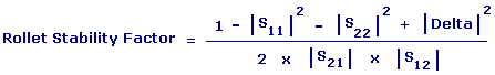
Rollet Stability Factor (K) of an amplifier was termed by John Rollett in 1962 in IRE paper titled Stability and Power-Gain
Invariants of Linear Twoports.
Rollet's stability factor is a one way to get an indication of whether you'll have a
problem or not. If K>1 then the device will be unconditionally stable for any combination of source and load
impedances. For K<1 the device is potentially unstable and will most likely oscillate with
certain combinations of source and load impedance.
The Maximum Allowable Gain (MAG) of a device is only
defined when Rollet Stability Factor is greater than 1. The Maximum Allowable Gain is the highest gain expected
to achieve from a conjugately matched amplifier.
L Network is a network composed of two branches in series, with the free ends connected to
one pair of terminals; the junction point and one free end are connected to another pair of
terminals. The disadvantage with L-networks is that they have a fixed Q, which is a function
of the ratio of the resistive parts of the two impedances which are being matched.
Q is important because it determines the bandwidth of the network.
The purpose of the matching networks is to transform the desired load and source impedances such
that they generate the calculated load and source impedances.
|